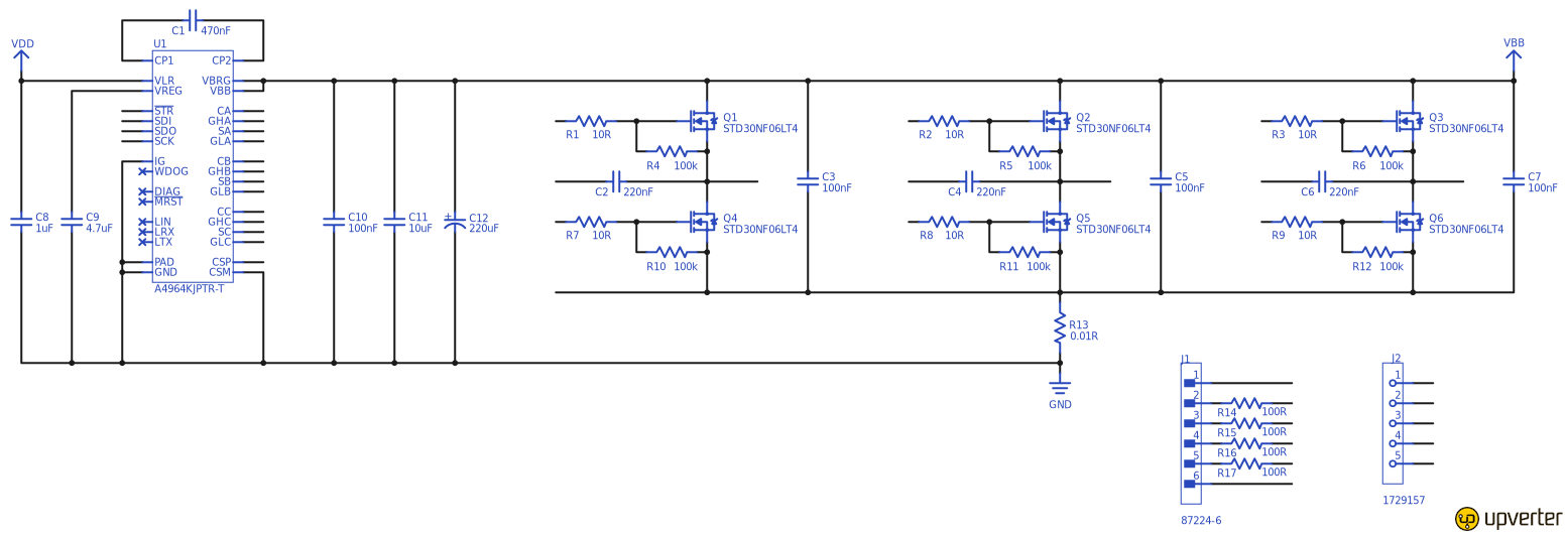
I’ve been playing with Upverter for the first time, and tried designing a (very) simple board with it. I’ve found a few issues and am slightly surprised that they haven’t been reported here before - possibly they were introduced relatively recently given that? I guess it makes most sense to create a separate thread for unrelated problems, so here’s a first one.
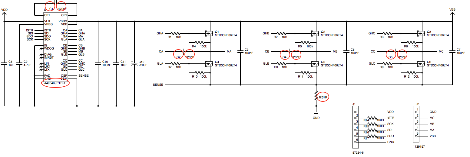
Exporting the schematic as PNG, SVG and PDF, I found that the PNG basically matched what was shown in the editor except the named net labels are all missing, making the schematic impossible to read. The net names are there on the SVG but the text placement is a bit haywire, and it’s all over the place in the PDF. Here are the PNG, SVG and PDF renderings of my test board to illustrate: I’ve circled a selection of the issues in red.


(Third image removed and moved to a follow up post as your forum software won’t allow more than two in a post. Probably a misconfiguration given the purpose of this forum…)
Apart from label positions being off, the SVG and PDF renderings also don’t translate the !STR into STR with an overbar. (I only circled this on the PDF rendering, but now I look, I see it’s wrong on the SVG too.)
The tiny board illustrating this is https://upverter.com/design/arachsys/2f0f1de6f7198bbe/ if you want to take a copy as an example of how to reproduce.
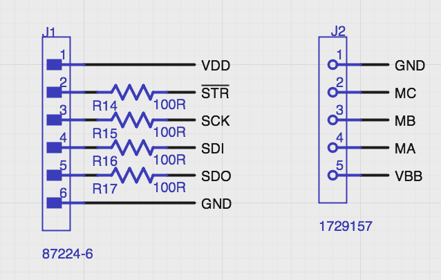
More generally, and straying into feedback rather than a straight bug report as above, I’ve found it quite hard to get label placement right on parts and on schematics. The part editor has a very coarse grid for label placement which can’t be overridden, generally giving you a choice between crashing the label into the part outline, or having it miles away where it’s likely to crash into adjacent parts when placed on a schematic. I notice that quite a few library parts have horrible label placement, presumably as a result of this. The two connectors in my schematic have label placement exactly as they came out of the library (as I haven’t tidied them up yet) which is pretty ugly.
(Fourth image removed too. Apologies to readers for breaking the flow by having to move these two images to a second post.)
In the above, the J1 and J2 labels at the top actually overlap/collide with the box, whereas the part numbers below are a long way away from it. Whilst one can fix this after placing the part in the schematic editor (whose grid for labels is much finer, or possibly not imposed at all? - consistency?), there’s no obvious way to fix it for every part of that type on the schematic, so I end up with subtly inconsistent label placement from part to part and a bit of a mess in the resulting render. Is downloading and hand-editing the JSON the best approach to fixing this for now?
Talking about the export/download page itself, two other minor irritations jump out at me:
-
Downloading png, svg, pdf, etc. files as one-entry .zip archives is very annoying. For a bundle of related files, sadly a .zip is still about the nicest thing you can do, but for a single file it’s quite unfriendly.
-
The naming of the zip file for download is very odd. My ‘Motor board’ project gets a zip file named ‘Motor-boardpng.zip’ with the ‘png’ crashing into the project title. Canonical naming of this would be ‘Motor-board.png.zip’ but ‘Motor-board-png.zip’ is another readable alternative if any platforms still have difficulties with a.b.c filenames?


