I have a motor controller design that I was hoping would be able to drive very high currents of 50A continuous up to 100A peak.
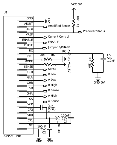
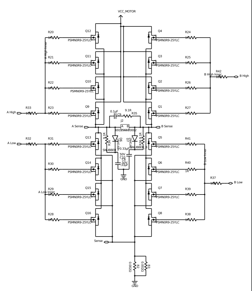
In order to do this, I have put 4 mosfets (PSMN0R9-25YLC: http://www.kynix.com/Detail/587415/PSMN0R9-25YLC.html) in parallel in each section of my h-bridge. I suspect this use of parallel mosfets may be part of my problem. I am using an Allegro A4956 mosfet driver (http://www.allegromicro.com/~/media/Files/Datasheets/A4956-Datasheet.ashx?la=en) to drive the mosfet gates. I have a 1 ohm resistor in series with each mosfet gate to keep them decoupled from each other (since I read some decoupling resistance was good practice) and a single 10 ohm resistor in series with the A4956 gate driving output. I am not sure if this series resistance is necessary, since it wasn’t shown in the example schematic in the A4956 data sheet, but I have seen in most other examples, and removing it didn’t seem to help either.
My problem is that the A4956 seems all too ready to go into fault mode for “overcurrent” (OCLn driven low and AIOUT above ground, and gate voltages too low for the high side to turn on but not grounded either). On occasion it reports a V_ds fault (OCLn driven low and AIOUT also grounded), but not nearly as often. I have assembled four of these circuits and they all have the same behavior, so I can tell the problem is with my design and not with any specific defective part.
This is puzzling to me because this happens even when no motor is attached, or when I manually pull the current sense voltage to ground.
However, if I use a low motor supply voltage of only 4V or so (my design is for 12V motors), the controller operates mostly correctly, only tripping to overcurrent if I make too sudden changes to the PWM duty cycle. But once I cross this arbitrary voltage, I am stuck in the overcurrent fault. I am using a power supply that reports amperage, so I know that when this is happening, there really isn’t any DC current going anywhere at all.
I thought that maybe the issue was the transient involved in turning on the mosfets, since 4 times the mosfets would require 4 times the current, but increasing the blank-time to a maximum did not seem to fix the issue. Perhaps using 12V instead of 4V also increases the current transient. When I look with an oscilloscope at the voltage on the mosfet gates, though, I don’t seem to see any transients occurring. To make sure enough current can be provided by the mosfet driver, I have used the current setting resistor R_Iset (set to 20k) to specify the maximum current, which should be 46.9mA to the high side and 88.5mA to the low side.
I think that 46.9mA should be plenty to charge the mosfet gates because running at 16kHz pwm, I should be able to charge up to 46.9mA / 16kHz / 2 = 1465nC and I should only need a maximum of 51nC (total gate charge of each mosfet) * 4 = 204nC total gate charge, nearly a full order of magnitude less.
I am pretty puzzled about what to try next and why the A4956 is not operating in any way I can understand.
edit: The most relevant sections are below, but the full project is public on upverter: https://upverter.com/acshi/43f3f94ec99df03a/53A-Motor-Controller-11/
Also, in testing the controller, I managed to blow out the indicator LEDs for when the motor is turned on and in what direction, which are just put across the output voltage. I find this also to be a very strange occurrence, but I don’t know if it is a related problem or a different one (like a voltage spike from when the motors were in fact turning at around 4V and then suddenly stopped).
A4956 part of the circuit Mosfet part of the circuit